5 MPLS VPN-概述
在公有网络上构建安全的私有网络。
5.1 专用网络

5.2 虚拟专用网络

运营商搭建的帧中继骨干网,穿越公有网络的虚链路。
5.3 VPN 术语
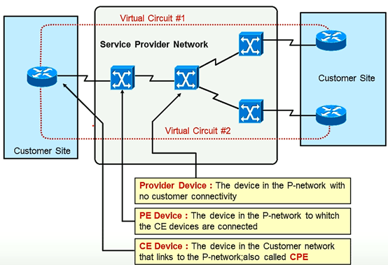
CE:客户端边界路由器;
PE:和CE直连的运营商设备,及运营商边界路由器;
P:不和CE直连,之和P和PE直连。
5.4 VPN 部署模型
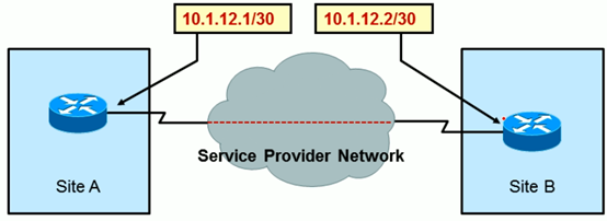
5.4.1 Overlay VPNS

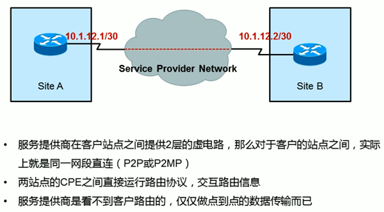
OVERLAY VPNS:即两端设备设备属于同一个子网,完全可以忽略中间运营商网络的存在,是可以直接PING通的。
如一个为10.1.1.1/32,另一端为10.1.1.2/32,不用关心运营商的网络
5.4.1.1 二层封装
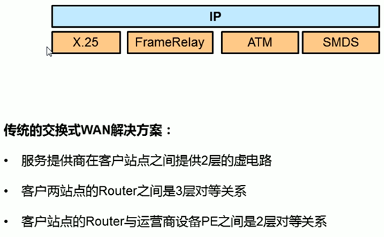
比较有代表性的二层封装为帧中继FRAMERELAY,提供二层虚链路。
5.4.1.2 IP隧道

R2(config-if)#tunnel mode ?
  aurp    AURP TunnelTalk AppleTalk encapsulation
  cayman  Cayman TunnelTalk AppleTalk encapsulation
  dvmrp   DVMRP multicast tunnel
  eon     EON compatible CLNS tunnel
  gre     generic route encapsulation protocol
  ipip    IP over IP encapsulation
  ipsec   IPSec tunnel encapsulation
  iptalk  Apple IPTalk encapsulation
  ipv6    Generic packet tunneling in IPv6
  ipv6ip  IPv6 over IP encapsulation
  mpls    MPLS encapsulations
  nos     IP over IP encapsulation (KA9Q/NOS compatible)
  rbscp   RBSCP in IP tunnel
IPIP:在原始IP前再加IP;
GRE:在IPIP基础上,即两个IP中间加GRE头,通用性更高,但是不加密。
IPSEC:加密,也是在两IP中间加头。
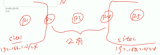
如私有192.168.1.0/24,访问192.168.2.0/24,私有地址需要穿越公有网络进行访问。如果不想做NAT,则可以在R2和R4之间搭建点到点隧道。
R1发出的IP包到R2后,R2发现需要进入隧道后,会在数据包压上新的IP头,源地址为R2地址,目的地址为R4地址。
R2路由到R4时,只查看外层IP头,到达R4后,拆除外层IP头,再把原始IP包送到目的网络。
5.4.1.3 三层路由
5.4.1.4 试验
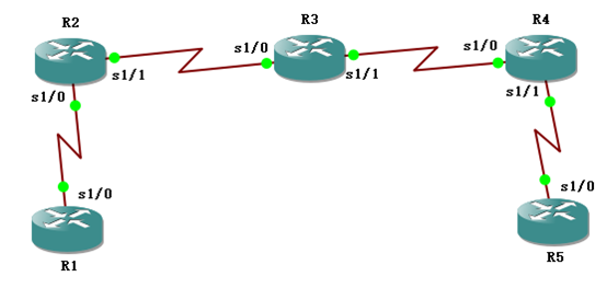
5.4.1.4.1 基础配置
R1配置,接口地址和默认路由
R1(config)#interface serial 1/0
R1(config-if)#ip address 192.168.1.1 255.255.255.0
R1(config-if)#no shutdown

R1(config)#ip route 0.0.0.0 0.0.0.0 192.168.1.254
R2配置,接口地址和默认路由
R2(config)#interface serial 1/0
R2(config-if)#ip address 192.168.1.254 255.255.255.0
R2(config-if)#no shutdown
R2(config)#interface serial 1/1
R2(config-if)#ip address 202.101.10.1 255.255.255.0
R2(config-if)#no shutdown

R2(config)#ip route 0.0.0.0 0.0.0.0 202.101.10.2
R3配置接口地址,不配置任何默认路由
R3(config)#interface serial 1/0
R3(config-if)#ip address 202.101.10.2 255.255.255.0
R3(config-if)#no shutdown
R3(config)#interface serial 1/1
R3(config-if)#ip address 202.101.20.1 255.255.255.0
R3(config-if)#no shutdown
R4配置接口及默认路由
R4(config)#interface serial 1/0
R4(config-if)#ip address 202.101.20.2 255.255.255.0
R4(config-if)#no shutdown
R4(config)#interface serial 1/1
R4(config-if)#ip address 192.168.2.254 255.255.255.0
R4(config-if)#no shutdown

R4(config)#ip route 0.0.0.0 0.0.0.0 202.101.20.1
R5配置接口地址及默认路由
R5(config)#interface serial 1/0
R5(config-if)#ip address 192.168.2.1 255.255.255.0
R5(config-if)#no shutdown

R5(config)#ip route 0.0.0.0 0.0.0.0 192.168.2.254
测试效果:
R1>ping 192.168.1.254
Type escape sequence to abort.
Sending 5, 100-byte ICMP Echos to 192.168.1.254, timeout is 2 seconds:
!!!!!
Success rate is 100 percent (5/5), round-trip min/avg/max = 4/20/36 ms
R1可以PING通网关
R2>ping 202.101.20.2
Type escape sequence to abort.
Sending 5, 100-byte ICMP Echos to 202.101.20.2, timeout is 2 seconds:
!!!!!
Success rate is 100 percent (5/5), round-trip min/avg/max = 40/59/76 ms
R2可以PING通R4
R1>ping 192.168.2.1
Type escape sequence to abort.
Sending 5, 100-byte ICMP Echos to 192.168.2.1, timeout is 2 seconds:
.....
Success rate is 0 percent (0/5)
但是R1是PING不同R5的
5.4.1.4.2 IP OVER IP-STATIC
下一步在R2和R4之间建隧道
建隧道前先要确保R2和R4之间是通的。即需要再202.101.10.1和202.101.20.2之间建隧道。即从202.101.10.1接口出去,从202.101.20.2接口出来。
R2上配置隧道源为:202.101.10.1,目的为202.101.20.2
从R1过来源为192.168.1.0的数据包,目的地址为192.168.20.0的数据包到来后,在R2会压上隧道源地址和隧道目的地址。
R2隧道配置,源地址和目的地址,模式使用IPIP
R2(config)#interface tunnel 0
R2(config-if)#tunnel source serial 1/1
R2(config-if)#tunnel destination 202.101.20.2
R2(config-if)#tunnel mode ipip
R4隧道配置
R4(config)#interface tunnel 0
R4(config-if)#tunnel source serial 1/0
R4(config-if)#tunnel destination 202.101.10.1
R4(config-if)#tunnel mode ipip
R4#show ip interface brief
Interface                  IP-Address      OK? Method Status                Protocol
FastEthernet0/0            unassigned      YES unset  administratively down down
GigabitEthernet0/1         unassigned      YES unset  administratively down down
GigabitEthernet0/2         unassigned      YES unset  administratively down down
GigabitEthernet0/3         unassigned      YES unset  administratively down down
Serial1/0                  202.101.20.2    YES manual up                    up
Serial1/1                  192.168.2.254   YES manual up                    up
Serial1/2                  unassigned      YES unset  administratively down down
Serial1/3                  unassigned      YES unset  administratively down down
SSLVPN-VIF0                unassigned      NO  unset  up                    up
Tunnel0                    unassigned      YES unset  up                    up
查看隧道TUNNUL0状态,已经启动。
给TUNNUL0两端接口配置地址,即类似隧道直连接口。
R2(config)#interface tunnel 0
R2(config-if)#ip address 1.1.1.1 255.255.255.0
R2(config-if)#no shutdown
R4(config)#interface tunnel 0
R4(config-if)#ip address 1.1.1.2 255.255.255.0
R4(config-if)#no shutdown
R2#show ip route
Codes: C - connected, S - static, R - RIP, M - mobile, B - BGP
       D - EIGRP, EX - EIGRP external, O - OSPF, IA - OSPF inter area
       N1 - OSPF NSSA external type 1, N2 - OSPF NSSA external type 2
       E1 - OSPF external type 1, E2 - OSPF external type 2
       i - IS-IS, su - IS-IS summary, L1 - IS-IS level-1, L2 - IS-IS level-2
       ia - IS-IS inter area, * - candidate default, U - per-user static route
       o - ODR, P - periodic downloaded static route

Gateway of last resort is 202.101.10.2 to network 0.0.0.0

     1.0.0.0/24 is subnetted, 1 subnets
C       1.1.1.0 is directly connected, Tunnel0
C    202.101.10.0/24 is directly connected, Serial1/1
C    192.168.1.0/24 is directly connected, Serial1/0
S*   0.0.0.0/0 [1/0] via 202.101.10.2
1.1.1.1隧道0为直连接口。
R2(config)#ip route 192.168.2.0 255.255.255.0 tunnel 0在R2上配置去往192.168.2.0网络,送往TUNNEL0
R4(config)#ip route 192.168.1.0 255.255.255.0 tunnel 0同时再R4也配置上。
当R1发送包去往R5时,达到R2后,根据默认路由进入TUNNEL0,由于之前模式设置的是IPIP,则在该数据包IP头前压入新的IP头,源目地址为TUNNEL0的源目地址。
R4#show ip route
Codes: C - connected, S - static, R - RIP, M - mobile, B - BGP
       D - EIGRP, EX - EIGRP external, O - OSPF, IA - OSPF inter area
       N1 - OSPF NSSA external type 1, N2 - OSPF NSSA external type 2
       E1 - OSPF external type 1, E2 - OSPF external type 2
       i - IS-IS, su - IS-IS summary, L1 - IS-IS level-1, L2 - IS-IS level-2
       ia - IS-IS inter area, * - candidate default, U - per-user static route
       o - ODR, P - periodic downloaded static route

Gateway of last resort is 202.101.20.1 to network 0.0.0.0

     1.0.0.0/24 is subnetted, 1 subnets
C       1.1.1.0 is directly connected, Tunnel0
C    202.101.20.0/24 is directly connected, Serial1/0
S    192.168.1.0/24 is directly connected, Tunnel0
C    192.168.2.0/24 is directly connected, Serial1/1
S*   0.0.0.0/0 [1/0] via 202.101.20.1
R4中有了静态路由:S 192.168.1.0/24 is directly connected, Tunnel0
R2#show ip route
Codes: C - connected, S - static, R - RIP, M - mobile, B - BGP
       D - EIGRP, EX - EIGRP external, O - OSPF, IA - OSPF inter area
       N1 - OSPF NSSA external type 1, N2 - OSPF NSSA external type 2
       E1 - OSPF external type 1, E2 - OSPF external type 2
       i - IS-IS, su - IS-IS summary, L1 - IS-IS level-1, L2 - IS-IS level-2
       ia - IS-IS inter area, * - candidate default, U - per-user static route
       o - ODR, P - periodic downloaded static route

Gateway of last resort is 202.101.10.2 to network 0.0.0.0

     1.0.0.0/24 is subnetted, 1 subnets
C       1.1.1.0 is directly connected, Tunnel0
C    202.101.10.0/24 is directly connected, Serial1/1
C    192.168.1.0/24 is directly connected, Serial1/0
S    192.168.2.0/24 is directly connected, Tunnel0
S*   0.0.0.0/0 [1/0] via 202.101.10.2
R2中也有了静态路由:S 192.168.2.0/24 is directly connected, Tunnel0
R3#show ip route
Codes: C - connected, S - static, R - RIP, M - mobile, B - BGP
       D - EIGRP, EX - EIGRP external, O - OSPF, IA - OSPF inter area
       N1 - OSPF NSSA external type 1, N2 - OSPF NSSA external type 2
       E1 - OSPF external type 1, E2 - OSPF external type 2
       i - IS-IS, su - IS-IS summary, L1 - IS-IS level-1, L2 - IS-IS level-2
       ia - IS-IS inter area, * - candidate default, U - per-user static route
       o - ODR, P - periodic downloaded static route

Gateway of last resort is not set

C    202.101.20.0/24 is directly connected, Serial1/1
C    202.101.10.0/24 is directly connected, Serial1/0
但是R3上没有任何关于192的路由,R3路由看的是外面新压入的TUNNEL0的源目地址。
R1>ping 192.168.2.1

Type escape sequence to abort.
Sending 5, 100-byte ICMP Echos to 192.168.2.1, timeout is 2 seconds:
!!!!!
Success rate is 100 percent (5/5), round-trip min/avg/max = 116/124/128 ms
这时就可以PING通了
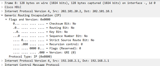
抓包分析新压入IP头,R2的S1/0口
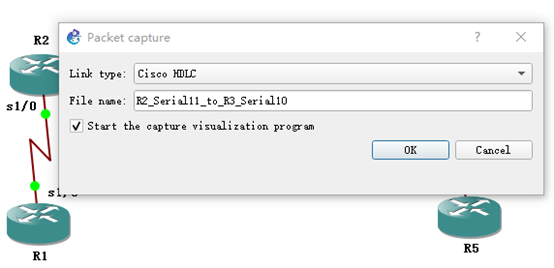
R1 PING R5,抓包
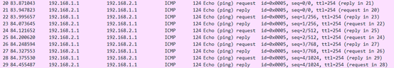
查看其中一条

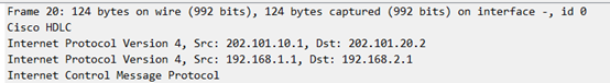
显示有两个IP头,
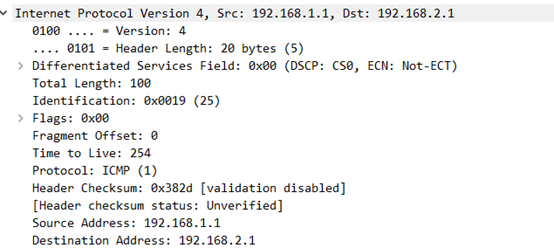
第一个是真实的源目地址,协议是ICMP
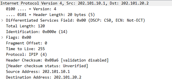
第二个是TUNNEL的源目地址,协议是IPIP
5.4.1.4.3 IP OVER IP-STATIC
还可以在TUNNEL0虚拟直连间运行动态路由协议,如OSPF。
关闭静态路由,运行OSPF
R2(config)#no ip route 192.168.2.0 255.255.255.0 tunnel 0
R4(config)#no ip route 192.168.1.0 255.255.255.0 tunnel 0
R2(config)#router ospf 1
R2(config-router)#network 192.168.1.254 0.0.0.0 area 0
R2(config-router)#network 1.1.1.1 0.0.0.0 area 0
R2启用OSPF,此处宣告的是TUNNEL接口地址
R4(config)#router ospf 1
R4(config-router)#network 192.168.2.254 0.0.0.0 area 0
R4(config-router)#network 1.1.1.2 0.0.0.0 area 0
R4启动OSPF,宣告TUNNEL地址
R4#show ip route
Codes: C - connected, S - static, R - RIP, M - mobile, B - BGP
       D - EIGRP, EX - EIGRP external, O - OSPF, IA - OSPF inter area
       N1 - OSPF NSSA external type 1, N2 - OSPF NSSA external type 2
       E1 - OSPF external type 1, E2 - OSPF external type 2
       i - IS-IS, su - IS-IS summary, L1 - IS-IS level-1, L2 - IS-IS level-2
       ia - IS-IS inter area, * - candidate default, U - per-user static route
       o - ODR, P - periodic downloaded static route

Gateway of last resort is 202.101.20.1 to network 0.0.0.0

     1.0.0.0/24 is subnetted, 1 subnets
C       1.1.1.0 is directly connected, Tunnel0
C    202.101.20.0/24 is directly connected, Serial1/0
O    192.168.1.0/24 [110/1064] via 1.1.1.1, 00:00:36, Tunnel0
C    192.168.2.0/24 is directly connected, Serial1/1
S*   0.0.0.0/0 [1/0] via 202.101.20.1
R4从1.1.1.1学到了去往192.168.1.0/24的路由,出接口为TUNNEL0
R5>ping 192.168.1.1

Type escape sequence to abort.
Sending 5, 100-byte ICMP Echos to 192.168.1.1, timeout is 2 seconds:
!!!!!
Success rate is 100 percent (5/5), round-trip min/avg/max = 104/116/132 ms
这时也可以PING通
通过TNUUNEL技术,不仅可以在公网间建立隧道,还可以在隧道间建立动态路由协议。
注意:不是所有协议都可以在IPIP上运行,比如IS-IS就不行,这时可以用GRE模式。
5.4.1.4.4 GRE
注意:不是所有协议都可以在IPIP上运行,比如IS-IS就不行,这时可以用GRE模式。
在两个IP头中间,压入GRE头。可以兼容更多的路由协议。
R2(config)#interface tunnel 0
R2(config-if)#tunnel mode gre ip
R4(config)#interface tunnel 0
R4(config-if)#tunnel mode gre ip
上面实验中,直接在R2R4中修改即可
R5>ping 192.168.1.1

Type escape sequence to abort.
Sending 5, 100-byte ICMP Echos to 192.168.1.1, timeout is 2 seconds:
!!!!!
Success rate is 100 percent (5/5), round-trip min/avg/max = 104/116/136 ms
也可以PING通
接着抓包分析GRE
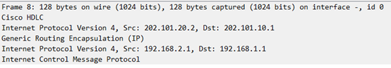
可以看出,在两个IP包头之间插入了新的GRE头
GRE头很简单,有个PROTOCOL字段指示上层字段封装的协议。
5.4.2 Peer-to-Peer VPNS

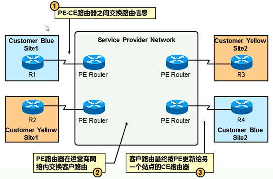
典型改动:CE和PE间是三层对等体关系,而OVERLAY则是CE和CE间是三层对等体关系。
CE把路由交给PE,具体内部怎么走,客户不管,由运营商收路由,做策略。客户不用管。
5.4.3 优缺点